Friday, November 12, 2010

Car launch 2010

Friday 12th November

Design boards: These are prints taken from our 2010 design report that is a submission required for the FSAE competition. They detail the design and manufacture processes that create our race car.

High Tech: The highly technical support method for our design board display, I think it worked well to create that motorsports feel.


Above: Drinks and nibbles supplied by the team, we enjoy giving back to those that give so much support to us.
 
What could it be? : Tim Keely from Science and Engineering marketing at Curtin University plays for the camera just before the event started. Tim is a great help to the team and just a great fan of our work. We often work together at events such as Open Day and Careers fair in Perth to really spread the word about the opportunities that exist with engineering at Curtin University.
Talk the talk: Nathan Staats (project manager), gives a short speech about the Twenty10 race car build and our hopes for FSAE-A this year in December.

Snap shot of the short video we played, it was a collection of photo's and time lapse film taken over the year during the build of our 2010 race car. Thanks goes to Greg Miller (mechatronic engineer on the team) for putting it together for us. We will upload the video to our website and YouTube page soon.
 
Marketing stands by management: Errol Hassett (left), marketing, and Nathan Staats (right), project manager. They have so far proved to be a great team for CMT in 2010, marketing and team direction have continued to progress towards continued improvement, great work guys.

Words from above: Tilak Chandratileke (Head of Department for Mechanical Engineering at Curtin University) gives his thoughts on CMT and this years car. Tilak and the department of mechanical engineering at Curtin university are a great support to have in our corner as we do our very best to show that Curtin really is producing some of the most innovative hard working engineers around.


CMT Twenty10

Thanks to all our sponsors and supporters this year, wish us the best of luck for FSAE-A this year.


Wednesday, November 10, 2010

Head needs a place to rest

As a part of the rules for the FSAE competition, the rest or head restraint of the race seat must be able to take a load of 80kg during an impact.

This is not really checked in any technical way, just a visual "will it work" type of check. We have had ours questioned before and s now we just put something in there that is meaty enough to look the business.

Having tried to cut down fabrication time by limiting on the fly designing, this part was modeled on computer along with the rest of the car in solidworks. Once we started to fabricate it up we noticed small problems still begin to pop up.

The design is basically a piece of 3mm thick steel plate that has been bent and cut to have an open trapezoidal shape, in which the head rest portion of the sit will sit an the most reward face of the seat should sit flush on the support.

First problem was being able to accurately make the bends. To get the desired radius the idea was to hit the plate around a tube of adequate diameter. Couldn't find a piece the right size so went slightly oversize to the closest I could find.

Next problem was insuring the bent was in the right location, I measured from the model and marked on the plate the end point of the bend arc and attempted to line this up in the vice. I used a spirit level to try and get the part and the temporary bending die at 90 degress to each other.


So the part seemed all set, and bending with the biggest hammer we had was quite quick and didn't take much force. I used an angle gauge to check the part as I bent it after every few strikes with the hammer, again attempting to keep a level datum I used the spirit level across the top of the bending die. It worked ok for what I thought the required accuracey was at this point, really it's just an eye ball check plus or minus 2 to 3 degrees, seemed ok to me.


Then we test fit the part in the car with the race seat in. At this point the race seat is still not mounted correctly because I would need to be able to use the chassis to fibreglass around the bars and we can't take the chassis anyway from the rest of the team for a whole day at this point so we're trying to do the best we can (this is dangerous because you basically can't get the seat to sit right at all unless you're just plain lucky and if you do get it in the right spot you definately won't get it in the right spot twice)

So we take a guess, trying to line the part up using a make shift plumbob to get the centre point, again not very accurate but we figured it was good enough for this particular part. Line it up on the bars and make a mark with a paint pen to show where we need to cut the excess length back for it to fit flush with the roll hoop.


Mistakes all over the place on this stage, not really centrlly placed and to fit it in there without it being cut means shifting the seat slightly out of place to be able to get the plate in there, this changes where the part fits also so is basically a total waste of time as I wold later find out.

Also a mistake made here due to rushing was that the plate was lined up on the front face of the roll hoop bar and not the rear face. The design in solidworks shows the part being almost a flush tagent fit with the rear face, a really basic error made there that does change the fit of the part quite drastically.

The cuts were made and the test fit then immediately showed a major error, the seat sat quite noticably out of position to get it to fit and then once the part was in the correct place there was a very large gap. Some adjustements to the bend angles were made by hand and then some other slight bends at the ends of the part were exerimented with to attempt a retro fit to use what we had now incorrectly fabricated.

This didn't work and at this point the part was looking like a total throw away and start again, it has fundemental failures in it and it will not mount correctly to the seat or the frame and if it is positioned to fit it then moves the seat so far out of position it risks making the drivers seating position not rules compliant.

Another leason learned again about trying to complete work in a rush. The model is so well done that it should have bee trusted and the length of the part made to match it as accurate as we could physically make it. If this was done it would have been picked up that the part was being mounted on the wrong face of the bar and perhaps the subsequent mistakes could have been avoided.

Really not an accpectable turn of events and I wish that it had ot happened, we are planning to salvage what we can of the part but it may be a full re-fabricaton job, there are some attempts being made now to solve the problem but it was a large motivation kiler for the morning.

A few points to myself for next time
  • Rule number 1: check the design before positioning
  • Rule number 2: check the design before you cut
  • Rule number 3: trust the design
  • Rule number 4: check the positioning of everything around the part that ineracts with it
  • Rule number 5: cut it, make it fit, if it doesn't fit, check the design, if it still doesn't fit.....make it fit.
I'm confident we will over come this small problem and still maintain a good quality level of work.

Sunday, November 7, 2010

Seat update....needs lots of adjustment

The seat is again proving to be a more challenging project than anticipated.

It has many rules governing it's position and size and so getting the belts to go through into the driver compartment is a tricky process. Also because we don't want to destroy the seat and cut holes where we don't need them it's hard to start to make cuts and holes when you really need the seat fully mounted in the chassis with a driver sitting in it to know exactly where these all go.

With the chassis unable to be soley used to mock this up at this late stage it is a bit of a guessing game, the solid works design used a model of a driver but there really is nothing liek the real thing so you can't trust this 100%.

Also makig life a little harder is the fact that the harness mounts are 30mm out of position due to a manufacturing error, it is too late to re-make these so we are using what we got but the seconday problems are just becoming a little be-motivating and slowing progress down.

I have decided that we are jst going to have t cut holes as best we can and keep cutting and shaping them till the seat sits right, we still have the mould so if need be we can add some patching to the composite lay-up later down the track once we know the belts will go where we want and comply with the rules.

Here is a few pics of the progress over the weekend...slow but now we have a pretty good game plan written down with a list of priorities to get done by our car launch this Friday, we just need it to be sitting in the car with belts through it so it looks the business, we can finalise the hard mounting points later.

Oh did I mention we all have exams over the next 3 weeks and the car goe on a truck to melbourne on the last day of exams ? This is the most fun you will have in you're engineering degree.


Above I use a drill bit that has the milling type teeth on it's shank so that I can easily cut complex curves. I start with lots of holes around the perimeter on the inside of where I want the final cut. I then mill between the holes joining them all up using the sideways cutting ability of the drill bit. Then I get a nice sharp half-round file and try to neaten up the edge. It works fairly well and is the most effective method I have found to do this type of work, I have been involved in the seat making in '08, '09 and this year so I'll building a knowledge of what NOT to do by making mistakes.....some would call it learning. Still got a lot to learn and still making mistakes but thats life, we do what we can.


Above test fitting the belt holes in the seat to see what will work and where we need adjustment. The lap belt holes (on the sides) should be ok I have marked where they need to be enlarged for the haress clips to fit through. The submarine (crotch) strap does fit through the opening but the belts will slightly rub on the seat at the moment which is no good, either have to cut the holes more to taper a slot towards the mount to enable a good angle of wrap around the drivers thighs or add a steel tube bar that just touches the underside of the seat, the belts would wrap around this so that they have a nice smooth radius transition up towards the driver, just have to ensure a good wrap around the drivers legs again though.

Saturday, November 6, 2010

Design Blunders

Just a short on to remind everyone we are human and we are all still learning.

We make mistakes.

With a miscommunication / understanding of how a particular laser cutter programed their CNC input in the machine we ended up with a double size part. With tight deadlines and long leadtimes associated with this type of work we opted to have the re-make plasma cut to save time.

The second generation part is not as accurate and has been slightly welded incorrected we now have a snow-ball effect with the harness mounts not sitting in the designed location withing the chassis.

This actually has strict rules within the technical criteria of the FSAE competition and it had to be double / triple checked that our car would still be compliant. LUCKY the design had inplace a few backups for suck errors with multiple locations for the harness eye-bolts to mount, this accomodated for the new further back position in the chassis.


The part on the left is the marginall under-sized plasma cut part (fully tig welded up here) and on the right is the double size part that was incorrectly laser cut due to an error on our end. (the part on the right is only roughly welded together as a gimic to ourselves to show the error that was made)

Just a reminder to us to be extra cautious even in times when we are pushed to make the car ready on time rushing small things can create much more hassel.

Even the marginally uder-size plasma cut part means that it now sits 30mm further back in the chassis even though the difference from design size to manufactured part is minimal it can create a big impact.

Body work and Cockpt liner update....we're almost there

It's hard to believe we have the car launch at the end of the week, Friday 12th Nov BUT we are quietly confident that with some huge efforts by the 'dirty dozen' within our team, everything should be sorted out without too many headaches.

In the good news we are really making good progress with composites.

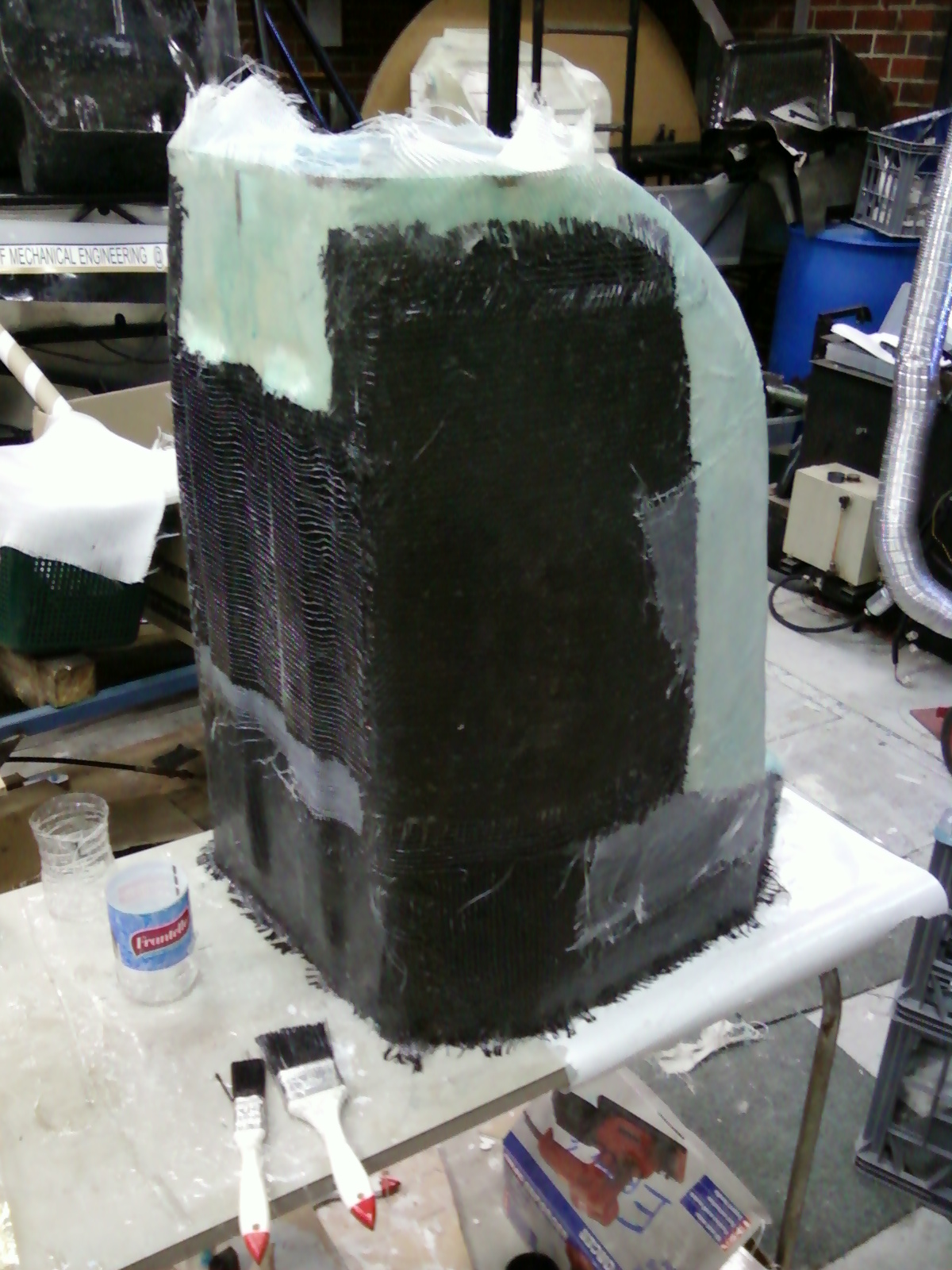
We'll start with the nose section of the cockpit liner, that was laid up today and test fitted in the chassis. It needs more work but is looking the goods (although it's a mongrel of a lay up using all kinds of scraps we had left in the workshop.....fingers crossed the final part is half decent)


Above you can see the assortment of fabrics used, some carbon, some fibreglass and some other cloth which I have forgotten the name just now.

Below you see what the mould looked like after we wrestled the part off it. We had to break the surface coating in places because it just would not budge, also have to run a split down the top of it to help spread it and peel it off. I will have to go back and splice this small section at the top front end of the liner later, we had half planed to do that because we anticipated it to be really hard to remove from the mould.


Below you will see or make shift heater / oven. The part came off slightly under-done so we had to try and cook it some more. We are pushing tight deadlines now so we didn't really have time to wait for it to fully sure. We took it off the mould while it was slightly still flexible, helped a little in removing it but we tried to stiffen it up a bit soon as we had test fitted it. We just draped it back over the mould and heated it with the heat gun under a plastic drop seat on one of our race car rolling stands.


Below The liner and the body are test fitted on the chassis.

Test fit view, if you are familiar with the FSAE competition you may know about the chassis sizing templates that must be passed through the interior of the car, the white / cream shape you can see above in the nose of the car is one of them being test fitted with the interior cockpit liner in place. So far we think we pass.....we'll see.

Below The body work on the male mould as Tim Stockton makes some cut aways of excess laminate. We hope to send it off to the painter tomorrow so it was a mad rush to try and get as much of the small fitting work done today.


Above Tim Stockton all gumbied up in PPE, looking like an extra from an early James Bond film or some kind of nuclear technician, Tim attacks the body work with a grinder to get the right shapes where needed.


Above MC (Michael Connaughton) our technical director for the last 2 years, takes a happy snap for his personal collection. Can you blame him, things are starting to look pretty tops.

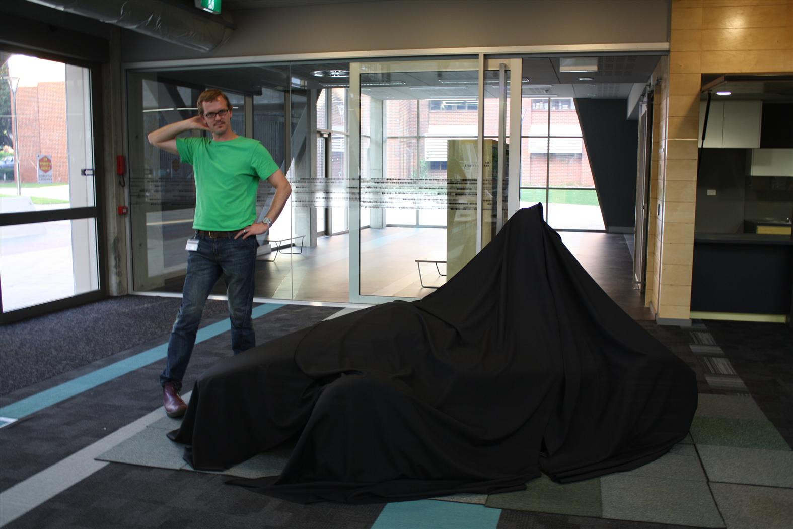
Here's what he was looking at, haha just something to lighten the mood.

Above Our black beauty, too bad this will almost all be painted over.


Below seat section of the liner has some marking on it made for holes to be cut for belts and gear shifter etc. Drill and an angle grinder do an OK job of cutting the shapes, final work is done with sand paper and then a rubber lip will be glued on to create a nice edge.

Below Tim Stockton can carry the male mould from the body work single handed. Apparently it is not that heavy. Looks great and he has done a stirling job over many months to create the male plug and then female moulds to finally produce the bodywork part. We think it's amazing he still smiles about being in the workshop after mid-night everytime he comes in to work on the car build......then again we're not really the average engineering students are we, you definately need a little something extra to stick at it.


Great surface finish has really made releasing the part much easier than in past years attempts at composite work. CMT helping the next generation of engineers to grow and develop their skills.....who'd have ever thought.


Still to come.......a list too big to bore you all to death with but the cockpit liner and ergonomics side of things (which is my baby.....Errol's)  is as follows.

Finalise the holes in the seat for the gear shifter, harness straps, sort out mounting points for the liner, finish the lay-up of the liner, possibly paint and coat the liner again, get the mirrors on the car, get the dash lay-up finished and sort out mounting it and try get the mechatronic guys to wire up the dash.

Bunch of welding for all the mounts, still need head restraint finalised (design is done just need some small fabrication work done in-house)

The list goes on.....but we'll make it.

Keep your eyes open and stay 'In Tune' with team progress.